

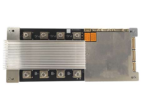
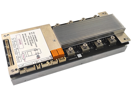
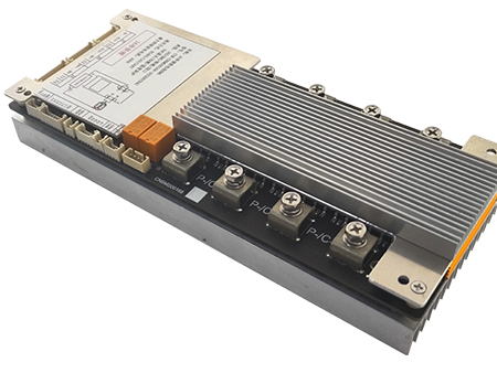
Battery Management Systm (BMS) with Communication protocol for 6~16 cells in series Li-ion/Li-Polymer/LiFePO4 Battery Packs
Features and Benefits
General Descriptions
|
Battery Pack Configurations |
6S – 16S |
|
Battery Pack Voltage |
15V -72V |
|
Battery Pack Capacity |
No Limit |
|
Continuous Discharge Current |
240A on-board Mosfets |
|
Discharge Peak Current |
260A for 10s lasting |
|
Over Discharge Current Protection |
Programmable |
|
Charge Current |
240A |
|
Over Charge Current Protection |
Programmable |
|
Temp. Sensors |
With 4 Sensors |
|
E-Switch/Ignition Switch |
YES |
|
Balancing Voltage |
Programmable |
|
Balancing Current |
50mA(optional) |
|
Isolated Communication Protocols |
CAN/RS485/UART |
|
Working Temp. |
-20°C ~ 80°C |
|
Dimension |
240 x 100 x 38mm |
|
Weight |
896g |
|
BMS comes with optional pre-charge resistor, optional fuse, harness, wires |
|
System Function Diagram

Please be noted the fuse is not coming with BMS, we suggest customer to have the fuse on the P+ cable, it is the last protection if after failures occurs on all BMS’s over-current-protections. Suggested to go with the fuse which is slightly greater than overcurrent protection current.
Programming Parameters Settings
Almost all parameters can be logically programmed according to your cells’ specs on BesTech Software (Supports Windows System only), please be noted the programming setting function is not open for everyone, the software normally is set as display for parameters only, BesTech Power only gives the access for programming to customers who really understand BMS/Battery well.
With watchdog embedded in BesTech Software, the system is more robust, Battery Pack parameters are real-time displaying on our PC software, the data detection frequency is every 400mS. Any alarm/fault conditions are saved to our EEPROM (Please be noted the special conditions records will be lost if BMS is reset or lost power).
To run BesTech Software, BesTech Programming Tool is needed (need purchase separately), the tool drive can be download from here.
Our programming tool is as below.

BesTech Software PC Utility (Windows only) downloading address is here. Your windows system probably need another firmware to run
smoothly, please download from here.
Here is the screenshot for BesTech Software PC utility.

Pre-configuration Before Use
BesTech BMS is preconfigured with your battery profiles which should be provided before ordering.
The basic battery profiles needed for pre-configuration as below.
• Li-ion / LiFePO4 • Configuration / Voltage
• Battery Cell LVC and HVC • Battery Pack Capacity
• Continuous discharge current • Charge current
• Battery cell temp. ranges • Over Current • Communication protocol and address (baud rate)
Any additional functions needed such as LCD/LED SOC display, buzz alarm, reset switch and so on, please contact us for functions customization, those are easy to implement from our firmware.
Thanks to our high advanced algorithms estimation, once the basic battery profiles are set initially, at least 2 completely cycles running, our BMS automatically starts to learn the parameters, voltage, current and temperature thresholds…, all parameters will be automatically calibrated and assigned. Those parameters can be adjusted according to the user’s needs afterward, but must remain within the Battery cell’s Manufacturer’s official specifications range.
* Once again the software utility normally is set as display for all parameters only, BesTech Power only gives the access for programming to customers who really understands BMS/Battery well.
Specifications
Taking LIFEPO4 Battery PACK BMS Parameters setting as example as below
|
No. |
Indicator items |
Factory default parameters |
Yes/No |
Notes |
||
|
1 |
Single-cell over charge protection |
Single-cell over charge alarm voltage |
3550mV |
Yes |
|
|
|
Single-cell over charge protection voltage |
3650mV |
Yes |
|
|||
|
Single-cell over charge protection delay |
1.0S |
Yes |
|
|||
|
Single-cell over charge protection release |
Single-cell over charge protection voltage release |
3550mV |
Yes |
|
||
|
Capacity release |
SOC<90% |
Yes |
|
|||
|
Discharge release |
Discharge current >200mA |
No |
|
|||
|
Single-cell over charge protection release delay |
3S |
Yes |
|
|||
|
2 |
Single-cell over discharge protection |
Single-cell over discharge alarm voltage |
2650mV |
Yes |
|
|
|
Single-cell over discharge protection voltage |
2500mV |
Yes |
|
|||
|
Single-cell over discharge protection delay |
1.5S |
Yes |
|
|||
|
Single-cell over discharge protection release |
Single-cell over discharge protection voltage release |
2800mV |
Yes |
|
||
|
Release while charging |
Charge current>200mA |
No |
|
|||
|
Single-cell over discharge protection release delay |
3S |
Yes |
|
|||
|
3 |
Charge over current protection |
Charge over current alarm current |
Customer customization |
Yes |
After appearing 3 times in a row, the locked state will no longer be automatically released, and the system needs to be restarted |
|
|
Charge over current protection current |
Customer customization |
Yes |
||||
|
Charge over current hardware protection overcurrent |
Set according to actual current |
Yes |
||||
|
Charge over current software protection delay |
1S |
Yes |
||||
|
Charge over current hardware protection delay |
10mS |
Yes |
||||
|
Charge over current protection release |
Automatically release |
Automatically release after 30s |
Yes |
|||
|
Discharge release |
Discharge current >200mA |
No |
||||
|
4 |
Discharge over current protection |
Discharge over current alarm current |
Customer customization |
Yes |
After appearing 3 times in a row, the locked state will no longer be automatically released, and the system needs to be restarted |
|
|
Discharge over current protection current |
Customer customization |
Yes |
||||
|
Discharge over current hardware protection overcurrent |
Set according to actual current |
Yes |
||||
|
1st discharge over current protection delay |
5S |
Yes |
||||
|
2nd discharge over current protection delay |
2S |
Yes |
||||
|
Discharge over current hardware protection delay |
10mS Duration to be confirmed |
Yes |
||||
|
Discharge over current protection release |
Automatically release |
Automatically release after 30s |
Yes |
|||
|
Charge release |
Charge current >200mA |
No |
||||
|
5 |
Short circuit protection |
Short circuit protection current |
Set according to actual current |
Yes |
After appearing 3 times in a row, the locked state will no longer be automatically released, and the system needs to be restarted |
|
|
Short circuit protection delay |
Hardware determination |
No |
||||
|
Short circuit protection release |
Released after 30s |
Yes |
||||
|
System restar |
||||||
|
MOS over temperature protection |
Over temperature protection temperature |
100℃ |
Yes |
|||
|
Over temperature release temperature |
80℃ |
Yes |
||||
|
6 |
Battery cell temp. protection |
Charge under temperature alarm temperature |
0℃ |
Yes |
|
|
|
Charge under temperature protection temperature |
-10℃ |
Yes |
|
|||
|
Charge under temperature protection release temperature |
0℃ |
Yes |
|
|||
|
Charge over temperature alarm signal |
55℃ |
Y |
|
|||
|
Charge over temperature protection temperature |
65℃ |
Yes |
|
|||
|
Charge over temperature protection release temperature |
55℃ |
Yes |
|
|||
|
Discharge under temperature alarm temperature |
-15℃ |
Yes |
|
|||
|
Discharge under temperature protection temperature |
-20℃ |
Yes |
|
|||
|
Discharge under temperature protection release temperature |
-15℃ |
Yes |
|
|||
|
Discharge over temperature alarm signal |
55℃ |
Yes |
|
|||
|
Discharge over temperature protection temperature |
65℃ |
Yes |
|
|||
|
Discharge over temperature protection release temperature |
60℃ |
Yes |
|
|||
|
7 |
Current consumption |
Active mode current consumption |
TBD |
No |
Determined by hardware |
|
|
Standby mode current consumption |
TBD |
No |
Determined by hardware |
|||
|
8 |
Balancing function |
Balancing starting voltage |
3500mV |
Yes |
|
|
|
Open Voltage difference |
100mV |
Yes |
|
|||
|
Close Voltage difference |
50mV |
Yes |
|
|||
|
9 |
Default capacity setting |
Low voltage warning threshold |
SOC<10% |
Yes |
No alarm when charging |
|
|
Full capacity setting |
?AH |
Yes |
|
|||
Connection Diagram

LED display, communication adapter board(optional)

Communication and address selection

Communication and address selection
Parallel operation and setting steps of battery packs
1 Turn off all battery packs, and connect the output positive and negative poles of all battery packs in parallel;
2 Connected in sequence via standard RS485 network cable(see picture above)
3 Set the PACK address in turn according to the picture below, and turn on all BMS in turn
4 View the BMS data of the corresponding address through the PC Utility software or in accordance with the communication protocol.
5 The battery pack BMS has a four-digit address dial switch, which is numbered according to the address from 0 to 15. The battery pack BMS should detect the
address of the dialer in real time, and the address of the dialer should be in binary mode

Single BMS mode
In single BMS mode, the dial switch must be 0000, and the BMS works independently
Multi-slave parallel communication mode
After the BMS is connected in parallel through RS485 communication, all BMSs are defaulted as slaves,and the external Master system uses the RS485 bus to
query all BMS data based on the system address of each slave. The external Master system collects and aggregates all data (need an external Master system).
Master-slave parallel communication mode
After the BMS is connected in parallel, the default number 0000 is the Master system, and the 0000 Master system is responsible for external data
communication, and is also responsible for collecting and processing the remaining BMS data.
Note: After parallel connection, due to the different internal resistance of each group of batteries, it is normal that the current and SOC of each group of batteries
are different. Generally, it is recommended to take the average value of SOC.
BMS Unit Connections

• Balancing Port – battery pack balancing sensing wires , 1st wire can be used as ON/OFF or reset
• External Temp. Sensors Port – 8 Pins connector for 4 x external sensors
• LED port for external systems such as SOC LED/LCD display, alarm buzzer… the definition of the sockets as the figure below.
Communication Protocols
BMS supports different communication protocols, HS006 integrated with 1x RS485, 1x RS232, 1x CANBus, 1x UART, all communications are isolated except for UART, the default baud rate used in current communication implementation is set as 19200KBPS, contact BesTech support for different baud rate setup, such as 9600K or others.
P.S. RS485, RS232, CAN communications can be used simultaneously.
Please download our communication address ID manual as below:
RS485
CANBus
BMS communicates with windows PC utility thru UART/RS485/CAN protocol, customer need purchase BesTech programming tool separately to do the programming and reading for all parameters.
Connection
